sugar
2 Pack TB6612FNG / DRV8833 Motor Driver Board Module – Compact High‑Performance Driver for Balancing Robots (Outperforms L298N)
2 Pack TB6612FNG / DRV8833 Motor Driver Board Module – Compact High‑Performance Driver for Balancing Robots (Outperforms L298N)
Couldn't load pickup availability
Product Description
This motor driver board uses modern dual H‑bridge ICs (TB6612FNG or DRV8833) to deliver efficient, low‑loss control of two DC motors or one small bipolar stepper motor in a compact form factor. Unlike older L298N modules that waste power as heat due to bipolar transistor outputs, these drivers use MOSFET H‑bridges with significantly lower voltage drop, giving your motors more usable voltage and torque from the same supply.
Each channel supports forward, reverse, and braking with PWM speed control, making this module a great fit for balancing robots, line followers, and other agile platforms that need responsive and cool‑running motor control. Its small footprint and low quiescent current also make it well suited for battery‑powered robots and portable devices.
Ideal Uses
-
Balancing robots and self‑balancing platforms where smooth, responsive motor control and low driver losses are critical.
-
Small robot cars and line followers using two DC gear motors.
-
Compact CNC/mini‑mechanism projects that need precise motor control without bulky drivers.
-
Upgrades from L298N in existing designs to improve efficiency, reduce heat, and gain more motor torque from the same supply.
Compatibility
- Works with Arduino, ESP32, ESP8266, and most 3.3 V or 5 V microcontrollers via standard logic‑level inputs (direction and PWM).
- Supports typical motor supply voltages for small DC motors (e.g., around 2–13 V depending on chip and module design; always check your board’s rating).
- Controls two DC motors independently or a single small bipolar stepper using both H‑bridges.
- Drop‑in replacement in many projects that currently use L298N, with fewer losses and a smaller board (pin mapping differs, but overall function is similar).
Key Features
- Dual H‑bridge motor driver (TB6612FNG or DRV8833) for two DC motors or one stepper.
- Modern MOSFET output stage with much lower voltage drop and heat generation than L298N‑type drivers.
- Forward, reverse, brake, and coast control modes per channel via simple IN/PHASE/PWM inputs (exact scheme depends on chip).
- PWM speed control up to tens of kHz, suitable for quiet, smooth motor operation.
- Continuous current capability in the hundreds of milliamps per channel (module‑dependent), with short‑duration peaks higher—ideal for small DC motors commonly used in balancing robots.
- Built‑in protection features in the driver IC, such as thermal shutdown and over‑current protection (varies by chip).
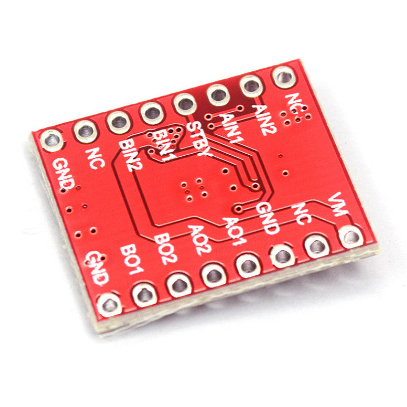
- Compact PCB with clearly labeled motor outputs, power inputs, and control pins for quick integration.
Technical Specs (Typical, Module‑Dependent)
- Values vary by whether the board uses TB6612FNG or DRV8833 and by manufacturer; always confirm your specific module:
- Driver IC: TB6612FNG or DRV8833 dual H‑bridge motor driver.
- Logic Voltage: typically 2.7–5.5 V (compatible with 3.3 V and 5 V MCUs).
- Motor Supply Voltage (VM): typically around 2–13 V range (check chip/module limits).
- Continuous Output Current: often ~1 A per channel (with suitable cooling), with higher short‑term peaks; many modules are conservatively used around 0.8–1 A per motor.
- Control Inputs:
- Direction/phase pins per channel.
- PWM input for speed control per channel (or shared, depending on design).
- Standby/enable pin on some TB6612FNG modules for low‑power mode.
- Channels: 2 independent DC motor channels, or combined to drive 1 bipolar stepper.
What’s Included
- 1 × TB6612FNG / DRV8833 Dual‑Channel Motor Driver Board Module
- 1 × Set of pin headers (often included loose, for optional soldering)
Safety Note
- Ensure your motor voltage and current stay within the driver and module ratings; exceeding them can trigger thermal shutdown or permanently damage the IC.
- Use a dedicated motor power supply and keep grounds common between the motors and controller, but avoid powering motors directly from a microcontroller’s regulator.
- Add appropriate decoupling capacitors near the motor power input and keep wiring short to reduce noise and voltage spikes from inductive loads.
- Double‑check polarity and wiring before powering the module, and never connect or disconnect motors while the system is energized to avoid damaging transients.
Share