sugar
PCA9685 16‑Channel PWM Servo Driver Module – I²C Robot Interface
PCA9685 16‑Channel PWM Servo Driver Module – I²C Robot Interface
Couldn't load pickup availability
PCA9685 16‑Channel PWM Servo Driver Module – I²C Robot Interface
Product Description
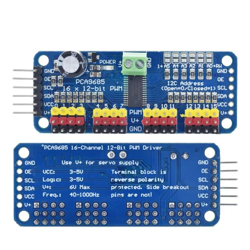
The PCA9685 16‑Channel PWM Servo Driver Module lets you control up to 16 independent PWM channels using just two I²C pins from your microcontroller. It’s perfect when you run out of hardware PWM outputs but still want to drive multiple servos, LEDs, or other PWM‑controlled devices in your robot or automation setup.
Because the PCA9685 includes its own on‑board clock, it generates PWM signals autonomously once configured, freeing your main MCU from the burden of continuous timing updates. You can also chain multiple modules on the same I²C bus using different addresses, enabling very large servo or LED arrays for complex robots, light shows, or multi‑axis control systems.
Compatibility
-
Works with Arduino boards (Uno, Nano, Mega, etc.) via I²C (SDA/SCL).
-
Fully compatible with ESP32, ESP32‑S3, and ESP32‑C6 boards at 3.3 V logic; the PCA9685 inputs are typically tolerant up to around 5–5.5 V.
-
Compatible with Raspberry Pi and other Linux SBCs using the I²C interface (perfect for robotics projects).
-
Supports most 3.3 V or 5 V microcontrollers that provide I²C; only two pins (SDA, SCL) are needed to control all 16 PWM outputs.
-
Key Features
-
16‑channel, 12‑bit PWM driver – provides high‑resolution pulse control for servos and LEDs.
-
I²C‑controlled – only two data lines needed to manage all outputs, leaving more pins free on your MCU.
-
Built‑in clock – runs PWM independently once configured; no continuous updates required from the microcontroller.
-
Adjustable PWM frequency up to around 1.6 kHz; 50–60 Hz is typical for hobby servos.
-
Chainable design – 6 address pins allow up to 62 modules on one I²C bus (up to 992 total channels for large servo/LED arrays).
-
5 V‑compliant outputs – can be driven from a 3.3 V microcontroller while safely switching up to around 5–6 V on the servo/LED power rail (V+).
-
Dedicated power input for servos (V+ terminal block or header), so high‑current loads don’t stress your microcontroller’s regulator.
-
Suitable as both a servo controller and a multi‑channel LED dimmer.
-
Technical Specs (Typical)
Values may vary slightly between manufacturers; check your specific module:
-
Controller IC: PCA9685, 16‑channel 12‑bit PWM driver.
-
Interface: I²C (Fast‑mode Plus capable, up to around 1 MHz in many designs).
-
MCU logic voltage: typically 3.3 V or 5 V compatible for SDA/SCL inputs.
-
PWM supply (V+): around 2.3–5.5 V typical for servos/LEDs on most breakout designs.
-
PWM frequency: adjustable up to ~1.6 kHz.
-
Resolution: 12‑bit (4096 steps) per channel.
-
Outputs: 16 channels, each supporting around 25 mA (for LEDs; servos draw power from V+, not through the PCA chip itself).
-
Address range: 0x40–0x7F using address pins to select unique addresses when chaining modules.
-
Ideal Uses
-
Robotics – control multiple servo joints in robot arms, quadrupeds, hexapods, and pan‑tilt rigs.
-
Animatronics – coordinated servo movement for props, displays, and interactive installations.
-
LED control – multi‑channel LED dimming, RGB/RGBA control, and light shows.
-
Home automation and IoT – driving servo‑based valves, vents, or mechanical indicators from a single controller.
-
Educational projects – demonstrating I²C, PWM, and multi‑axis motion control in microcontroller courses.
-
What’s Included
-
1 × PCA9685 16‑Channel PWM Servo Driver Module
-
(Variants may also include) terminal block for V+ power, pin headers for servo outputs and I²C connection, depending on the specific supplier design.
Safety Note
-
The PCA9685 module does not regulate servo power voltage; always supply a suitable servo voltage (commonly 5–6 V) on V+ and ensure it matches your servos’ specifications.
-
Servos can draw significant current; use an external power supply sized appropriately, and always share a common ground between the servo supply and your microcontroller.
-
Avoid powering servos directly from a microcontroller’s USB or on‑board regulator, as this can cause resets or damage due to over‑current.
-
Double‑check I²C wiring (SDA/SCL) and module orientation before powering the system to prevent short circuits or bus conflicts.
-
-
-
-
Share