sugar
2 Pack MPU6500 GY‑6500 6DOF & MPU‑9250 GY‑9250 9‑Axis IMU Sensor Modules – I²C/SPI Motion Tracking
2 Pack MPU6500 GY‑6500 6DOF & MPU‑9250 GY‑9250 9‑Axis IMU Sensor Modules – I²C/SPI Motion Tracking
Couldn't load pickup availability
Product Description
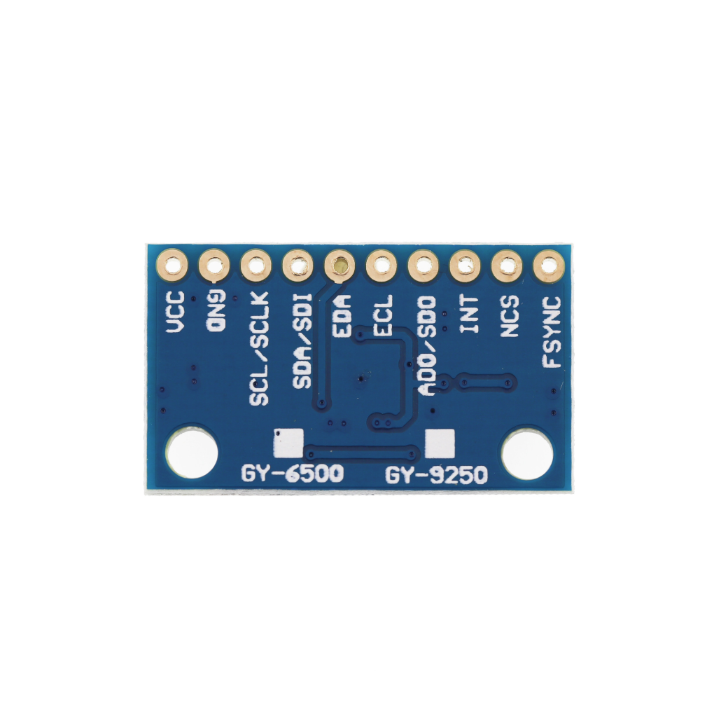
These IMU sensor modules provide flexible motion tracking solutions in a small form factor. The MPU6500 GY‑6500 6DOF module integrates a 3‑axis accelerometer and 3‑axis gyroscope, delivering high‑precision 6‑axis motion data for attitude, tilt, and vibration measurements. It is a modern, low‑power upgrade path to classic MPU6050‑style projects, with support for both I²C and SPI interfaces and a built‑in Digital Motion Processor (DMP) for on‑chip motion fusion.
The MPU‑9250 GY‑9250 9‑Axis module adds a 3‑axis magnetometer to the same core gyroscope/accelerometer, providing complete 9‑DOF sensing (3‑axis gyro + 3‑axis accel + 3‑axis mag) in a single package. Its integrated DMP and dedicated sensor bus enable efficient fusion of all three sensor types, producing stable orientation and heading data for drones, robots, VR controllers, and navigation systems. Both modules expose standard pin headers and work with a wide range of microcontrollers and open‑source libraries.
Ideal Uses
-
Robotics and drones needing attitude stabilization, orientation, and heading (especially with the 9‑axis GY‑9250).
-
Navigation and motion‑tracking systems such as self‑balancing robots, gimbals, and handheld IMUs.
-
VR/AR input devices and controllers that require 3D orientation and motion sensing.
-
Data logging and analysis of vibration, tilt, and movement for mechanical systems or wearables.
-
Educational projects demonstrating 6‑axis vs 9‑axis IMUs, sensor fusion, and I²C/SPI communication.
Compatibility
- GY‑6500 modules are typically powered from 3–5 V thanks to on‑board regulation and level adaptation, while the MPU‑6500 core itself is a low‑voltage device.
- GY‑9250 modules generally operate at 3.3 V logic and supply, and are commonly used with Arduino, Raspberry Pi, and ESP32 via I²C up to 400 kHz or SPI around 1–20 MHz (chip‑level).
- Supported by numerous Arduino and Python libraries (e.g., MPU9250/MPU6500 drivers and sensor‑fusion examples) and integration guides from community and vendor resources.
Key Features
GY‑6500 – MPU6500 6DOF Module
- 6 Degrees of Freedom (6DOF): 3‑axis accelerometer + 3‑axis gyroscope.
- Gyro full‑scale ranges: ±250, ±500, ±1000, ±2000 °/s.
-
Accelerometer ranges: ±2 g, ±4 g, ±8 g, ±16 g.
GY‑9250 – MPU‑9250 9‑Axis Module
1 × MPU‑9250 GY‑9250 9‑Axis IMU Sensor Module (gyroscope, accelerometer, magnetometer; pre‑soldered headers on some versions).9 Degrees of Freedom (9DOF): 3‑axis gyro + 3‑axis accelerometer + 3‑axis magnetometer.
Gyro ranges: ±250, ±500, ±1000, ±2000 °/s.
Accelerometer ranges: ±2 g, ±4 g, ±8 g, ±16 g.
Magnetometer range: up to around ±4800 µT, suitable for compass/heading applications.
On‑chip DMP and MotionFusion for 9‑axis orientation and heading outputs.
I²C and SPI interfaces, with support for up to 400 kHz I²C and higher‑speed SPI for sensor and interrupt registers.
Technical Specs (Typical, Module‑Dependent)
GY‑6500 (MPU6500)
Chip: MPU‑6500 6‑axis MotionTracking device.
Accel Ranges: ±2/±4/±8/±16 g (programmable).
Gyro Ranges: ±250/±500/±1000/±2000 °/s (programmable).
Supply Voltage (module): typically 3–5 V (on‑board regulator), with core operating ~1.71–3.6 V.
Communication: I²C (up to ~400 kHz) or SPI.
Features: DMP, digital temperature sensor, programmable interrupts for gestures and motion events.
GY‑9250 (MPU‑9250)
-
Chip: MPU‑9250 9‑axis MotionTracking device.
-
Accel Ranges: ±2/±4/±8/±16 g.
-
Gyro Ranges: ±250/±500/±1000/±2000 °/s.
-
Magnetometer Range: up to ±4800 µT.
-
Supply Voltage (chip): 2.4–3.6 V (modules typically run at ~3.3 V).
-
Interfaces: I²C and SPI, with I²C up to 400 kHz and SPI up to 1–20 MHz depending on registers.
-
Extras: auxiliary I²C bus for external sensors, temperature sensor, and run‑time calibration firmware.
What’s Included
1 × MPU6500 GY‑6500 6DOF 6‑Axis Accelerometer & Gyroscope Sensor Module (with pin headers, depending on variant).
Safety Note
-
Both modules are 3.3 V–domain devices at the chip level; even if the breakout accepts 5 V, always verify whether your board includes a regulator and level shifting before connecting to 5 V systems.
-
For accurate orientation, you must perform proper calibration of accelerometer, gyroscope, and magnetometer, and avoid placing the modules near strong magnetic fields or high‑current conductors that can distort readings.
-
In safety‑critical applications (e.g., flight control), treat these IMUs as part of a redundant sensor suite and thoroughly test sensor‑fusion and failure modes before deployment.
-
Both GY‑6500 and GY‑9250 support I²C and SPI digital interfaces, allowing flexible connection to Arduino, ESP32, STM32, and similar controllers.
-
Share