sugar
GY‑87 10DOF Sensor Module – MPU6050 HMC5883L BMP180 IMU Board
GY‑87 10DOF Sensor Module – MPU6050 HMC5883L BMP180 IMU Board
Couldn't load pickup availability
Product Description
The GY‑87 sensor module integrates three key sensors into one compact 10‑DOF board: an MPU6050 3‑axis accelerometer and 3‑axis gyroscope, an HMC5883L (or compatible QMC5883L) 3‑axis magnetometer, and a BMP180 barometric pressure and temperature sensor. Together, they provide acceleration, angular velocity, magnetic heading, and altitude/pressure data, making the module a complete motion and environment sensing solution for embedded projects.
All sensors share a common I²C bus, and the board includes on‑board regulation, filters, and I²C level shifting so it can be used safely with 3.3 V or 5 V microcontroller systems. With proper sensor fusion (e.g., complementary or Kalman filters), the GY‑87 can deliver stable orientation (pitch/roll/yaw) and altitude estimates for drones, robots, and navigation systems.
Ideal Uses
- Multirotor drones and RC aircraft needing attitude, heading, and altitude information for stabilization and navigation.
- Robotics and mobile platforms that require 3D orientation, tilt compensation, and compass‑based heading.
- Navigation and tracking systems (e.g., handheld IMUs, boat or vehicle instruments, data loggers).
- Weather and environment monitors combining pressure, temperature, and motion data.
- Educational projects demonstrating sensor fusion, I²C communication, and multi‑sensor IMUs.
Compatibility
- Interfaces via I²C (SDA/SCL), compatible with Arduino, ESP32, ESP8266, STM32, and other microcontrollers.
- Many GY‑87 boards support 3–5 V input, thanks to on‑board 3.3 V regulator and I²C level shifter—safe to use with 5 V Arduino boards and 3.3 V ESP32 systems (check pin labels).
- Works with Raspberry Pi and other SBCs using I²C for full 10‑DOF data acquisition.
- Supported by widely available libraries for MPU6050, HMC5883L/QMC5883L, and BMP180/BMP085, with many example projects and tutorials.
Key Features
MPU6050 6‑axis IMU: 3‑axis accelerometer + 3‑axis gyroscope with on‑board Digital Motion Processor (DMP) and user‑programmable ranges.
HMC5883L / QMC5883L 3‑axis magnetometer: digital compass for heading and magnetic field measurements.
BMP180/BMP085 barometric sensor: high‑resolution barometric pressure and temperature readings for altitude estimation and weather monitoring.
All sensors connected to a shared I²C bus, with separate interrupt/data‑ready pins exposed for advanced use.
On‑board ultra‑low noise linear LDO regulator, filters, and I²C level converter, improving noise immunity and 5 V compatibility.
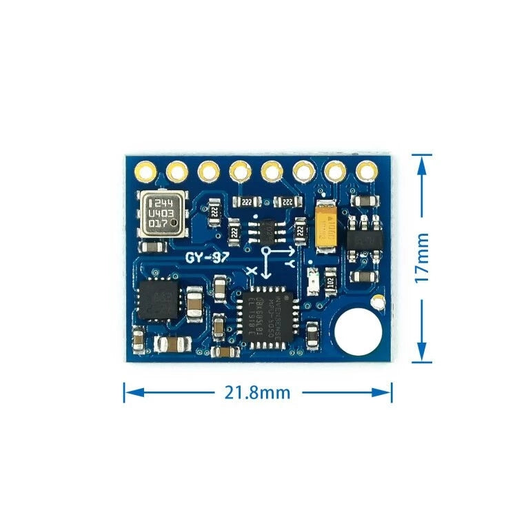
Compact PCB (around 22 × 17 mm) with clearly labeled pins and mounting holes for integration into flight controllers and robot boards.
Technical Specs (Typical, GY‑87 / 10DOF)
- Exact values depend on board revision and specific sensor variants:
- Driver Chips: MPU6050 + HMC5883L (or QMC5883L) + BMP180/BMP085.
- Operating Voltage: 3 to 5 V input on many modules; on‑board regulator provides 3.3 V to sensors.
- Communication: I²C (SCL, SDA), with extra pins for FSYNC, INT (MPU6050), and DRDY (magnetometer).
- MPU6050 (IMU):
- Gyro ranges: ±250 / ±500 / ±1000 / ±2000 °/s (programmable).
- Accelerometer ranges: ±2 / ±4 / ±8 / ±16 g (programmable).
- HMC5883L / QMC5883L (Magnetometer):
- 3‑axis magnetic field measurement for compass/heading applications.
- BMP180/BMP085 (Barometric sensor):
- Pressure range and resolution suitable for meter‑level altitude changes (e.g., flight and weather monitoring).
- Board Dimensions & Misc:
- Size: ~22 mm × 17 mm; weight around 5 g.
- I²C‑address selection for MPU6050 via solder jumpers on some boards.
What’s Included
- 1 × GY‑87 10DOF Sensor Module (MPU6050 + HMC5883L/QMC5883L + BMP180/BMP085)
(Some variants may include pin headers to solder, depending on supplier.)
Safety Note
- Ensure you respect the 3.3 V domain of the sensors; while the board typically supports 5 V input thanks to its regulator and level shifter, bypassing these (e.g., feeding 5 V directly into 3.3 V pins) can damage the sensors.
- For accurate orientation and heading, perform proper calibration of the accelerometer, gyroscope, and magnetometer, and avoid placing the module near strong magnetic fields or high‑current wiring that can distort readings.
- In flight or navigation applications, always test thoroughly and use redundancy where safety is critical; treat the GY‑87 as part of a broader sensor and control system, not a single point of truth.
Share