sugar
2 Pack GY‑50 L3G4200D 3‑Axis Digital Gyroscope Sensor – Angular Velocity Module
2 Pack GY‑50 L3G4200D 3‑Axis Digital Gyroscope Sensor – Angular Velocity Module
Couldn't load pickup availability
2 Pack GY‑50 L3G4200D 3‑Axis Digital Gyroscope Sensor – Angular Velocity Module
Product Description
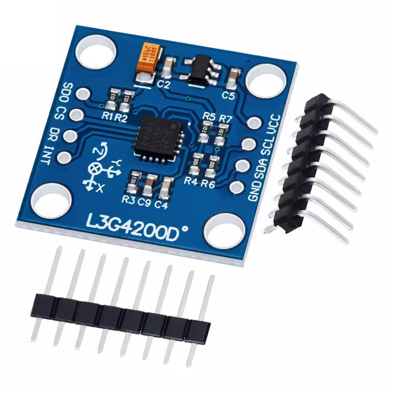
The GY‑50 L3G4200D sensor module is a low‑power, 3‑axis digital gyroscope designed to measure angular velocity around the X, Y, and Z axes. Built around ST’s L3G4200D chip, it offers selectable full‑scale ranges of ±250, ±500, or ±2000 degrees per second (dps) with 16‑bit rate output and a user‑selectable bandwidth, making it suitable for both slow‑ and fast‑motion applications.
The module communicates via I²C or SPI, and many breakout boards include address jumpers and a 32‑sample FIFO buffer to offload data collection from the host microcontroller. An integrated temperature sensor and power‑down/sleep modes help with drift tracking and low‑power operation. This combination makes the GY‑50 a solid choice for robotics, VR controllers, IMUs (when combined with accelerometers), and other motion‑sensing systems.
Ideal Uses
-
Robotics and drones for measuring angular rate in stabilization and navigation systems.
-
Gaming and VR/AR input devices, capturing rotation and gestures for controllers or head tracking.
-
Inertial navigation when combined with accelerometers and magnetometers as part of a full IMU.
-
Motion analysis and data logging for mechanical systems, platforms, or experimental rigs.
-
Educational projects demonstrating gyroscopes, digital sensors, and I²C/SPI communication.
-
Compatibility
-
Works with Arduino, ESP32, ESP8266, and other microcontrollers via I²C or SPI digital interfaces.
-
Typical operating voltage range of 3–5 V on many GY‑50 modules, even though the L3G4200D chip core itself is specified for 2.4–3.6 V; most breakouts include regulation and level adaptation (confirm your specific board).
-
Compatible with Raspberry Pi and other single‑board computers using I²C (up to ~400 kHz) or SPI (up to ~10 MHz) for gyro data.
-
Can be combined with accelerometer and magnetometer modules to form a multi‑sensor IMU stack for full 9‑DOF motion tracking.
-
Key Features
-
3‑axis digital gyroscope measuring angular rate around X, Y, and Z axes.
-
Selectable full‑scale ranges: ±250, ±500, ±2000 dps (degrees per second).
-
Digital outputs over I²C or SPI with 16‑bit rate value data and 8‑bit temperature data.
-
Integrated 32‑sample FIFO buffer for burst reads and reduced host polling overhead.
-
Embedded temperature sensor, power‑down, and sleep modes for drift monitoring and low‑power operation.
-
Designed for low‑power operation with good zero‑rate and sensitivity stability over temperature and time.
-
High shock survivability, suitable for handheld and mobile devices.
-
Technical Specs (Typical, GY‑50 / L3G4200D)
Exact values may vary slightly by module vendor; consult your specific board’s documentation.
-
Chip: L3G4200D 3‑axis digital output gyroscope.
-
Gyro Range (selectable): ±250 / ±500 / ±2000 dps.
-
Data Output: 16‑bit angular rate values, 8‑bit temperature output.
-
Interfaces: I²C (up to ~400 kHz) or SPI (up to ~10 MHz, 3‑ or 4‑wire).
-
Supply Voltage (chip): 2.4 V to 3.6 V; modules often accept 3–5 V via on‑board regulation.
-
IO Voltage: low‑voltage‑compatible IOs (around 1.8 V internal spec).
-
Operating Temperature: −40 °C to +85 °C.
-
FIFO Buffer: 32‑sample first‑in‑first‑out (FIFO) for rate data.
-
Package (chip): small LGA; module is typically a small PCB suitable for breadboards and headers.
-
What’s Included
-
1 × GY‑50 L3G4200D 3‑Axis Digital Gyroscope Sensor Module
(Some variants may also include pin headers or mounting hardware depending on supplier.)
-
-
Safety Note
-
Ensure the supply voltage and logic levels match your module’s specifications; some GY‑50 boards accept 5 V input, but the L3G4200D chip itself is a 3.3 V device—check whether your board includes a regulator and level shifting before connecting.
-
Avoid excessive mechanical shock or vibration beyond the sensor’s rated survivability; while robust, severe impacts can affect calibration or damage the module.
-
In navigation or safety‑critical applications, always combine the gyroscope with additional sensors (accelerometer, magnetometer, or external references) and appropriate filtering; do not rely on the gyro alone for critical attitude control.
-
-
-
-
Share