sugar
2 Pack CNC Shield V3 Expansion Board – For Engraving Machines & 3D Printers (Compatible with A4988 Driver Modules)
2 Pack CNC Shield V3 Expansion Board – For Engraving Machines & 3D Printers (Compatible with A4988 Driver Modules)
Couldn't load pickup availability
Product Description
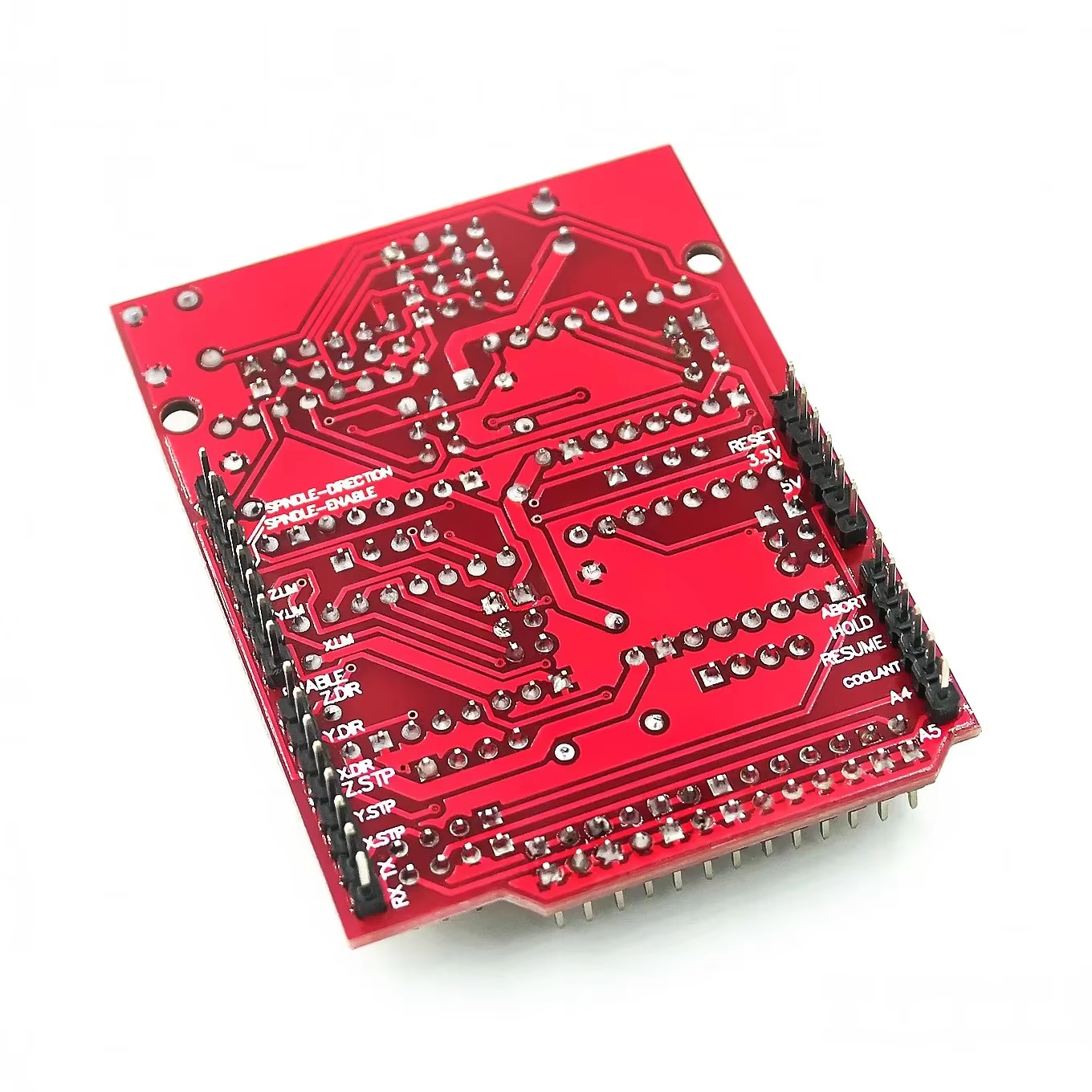
The CNC Shield V3 Expansion Board is a compact stepper‑motor control shield that plugs directly onto an Arduino Uno‑style board to create a standalone CNC or basic 3D‑printer controller. It provides four sockets for A4988‑compatible stepper drivers (such as A4988 or DRV8825), allowing you to drive up to four stepper motors for X, Y, Z, and a duplicated or fourth axis.
Designed around the popular GRBL firmware, the shield exposes pins for two endstops per axis, spindle and coolant control, and microstepping configuration via jumpers. Stepper motors connect via 4‑pin headers or screw terminals, and a separate motor power input supports typical CNC and 3D‑printer voltages in the 12–36 V range (driver‑dependent), making this board a flexible foundation for desktop CNC, laser engravers, and motion‑control projects.
Ideal Uses
-
Desktop CNC routers and engraving machines using NEMA 17 or similar steppers for X/Y/Z axes.
-
Basic 3D printers and DIY motion platforms controlled by GRBL or custom Arduino firmware.
-
Laser engravers and plotters where precise multi‑axis stepper control is required.
-
Educational projects exploring G‑code, GRBL, and stepper motor control with A4988/DRV8825 drivers.
Compatibility
- Arduino‑compatible: designed to plug onto Arduino Uno‑form‑factor boards and work with GRBL (e.g., GRBL 0.8/0.9/1.x, depending on shield revision).
- Supports A4988‑compatible stepper drivers, including A4988 and DRV8825 (and similar Pololu‑style modules).
- Up to four stepper drivers for X, Y, Z, and an additional A axis that can clone an axis or act as a fourth axis with custom firmware.
- Motor supply typically 12–36 V DC, limited by the installed driver modules (A4988 usually up to 35 V; DRV8825 up to ~45 V; follow driver datasheet).
Key Features
- Four driver sockets for A4988‑compatible stepper driver modules, enabling control of up to 4 stepper motors.
- 4‑axis support: X, Y, Z, plus A (clone of X/Y/Z or independent axis with custom firmware).
- Two endstop inputs per axis (6 total), supporting min/max switches for X, Y, and Z.
- Spindle enable/direction and coolant outputs for controlling relays, MOSFETs, or spindle drivers.
- Microstepping jumpers under each driver socket to configure step resolution (e.g., up to 1/16 for A4988, 1/32 for DRV8825).
- Separate terminals for motor power (12–36 V) and logic power via the Arduino, allowing appropriate supplies for both.
- Stepper outputs via 4‑pin headers or screw terminals, suitable for NEMA 17/23‑style motors.
- Compact shield footprint that sits directly on the Arduino Uno, minimizing wiring and making assembly cleaner.
Technical Specs (Typical, CNC Shield V3)
Exact details may vary slightly between manufacturers and revisions:
- Shield Version: CNC Shield V3.x for Arduino Uno.
- Supported Drivers: A4988, DRV8825, and compatible Pololu‑style modules.
- Number of Axes: 4 (X, Y, Z, A).
- Motor Supply Voltage: typically 12–36 V DC (limited by installed drivers).
- Logic Voltage: typically 5 V via Arduino; drivers accept 3.3/5 V logic depending on type (A4988/DRV8825 support both).
- Endstops: up to 2 per axis (X‑min/X‑max, Y‑min/Y‑max, Z‑min/Z‑max).
- Firmware: commonly used with GRBL (open‑source G‑code interpreter for Arduino Uno).
- Board Size: approx. 68 × 53 × 18 mm (typical for many CNC Shield V3 boards).
- What’s Included
- 1 × CNC Shield V3 Expansion Board (A4988 driver modules typically sold separately).
(Some kits may include A4988/DRV8825 drivers and heatsinks; check specific product options.)
Safety Note
- Always insert A4988/DRV8825 driver modules in the correct orientation; misalignment (e.g., reversed EN pin) can instantly damage the drivers and shield.
- Set the current limit on each driver (using the Vref potentiometer and datasheet formulas) to match your stepper motors; over‑current can cause overheating and thermal shutdown or permanent damage.
- Use an appropriate motor power supply (e.g., 12–24 V for NEMA 17 steppers) and ensure total current draw stays within the supply and driver limits.
- Keep fingers and conductive objects away from the shield while powered, especially around exposed driver modules and motor terminals, to avoid short circuits and injury from moving mechanical parts.
Share